Here is a general guide to creating and IPsec tunnel between two Cisco routers. This can also be applied to other devices as the concepts the same, but your configuration on those devices might be a little different.
Basic Configuration of Routers
Assign IP Addresses: Ensure both routers have IP Addresses assigned to their interfaces
Configure Routing: Setup Routing (static or dynamic) so the routers know how to reach each other.
Configure ISAKMP (IKE) Policy
ISAKMP (Internet Security Association and Key Management Protocol) policies define how the routers will establish the Phase 1 security associations (SA’s)
Set ISAKMP Policy: Define encryption (AES/3DES), hash (SHA,MD5), authentication (pre-shared keys), group (Deffie-Hellman group), and lifetime values.
The crypto map binds the previous elements together and applies them to the interface.
Create crypto map: Associate the ISAKMP policy, transform set, peer and ACL.
R1(config)# crypto map MYMAP 10 ipsec-isakmp
R1(config-crypto-map)# set peer [peer IP address]
R1(config-crypto-map)# set transform-set MYSET
R1(config-crypto-map)# match address 100
Apply Crypto Map to the Interface
Bind to the Interface: Apply the crypto map to the interface facing the remote site.
Verify configuration: Use these commands like “show crypto isakmp sa”, “show crypto ipsec sa” to check the status of the tunnels
This is a very generic guide on establishing an IPsec tunnel between two Cisco Routers, your requirements might be different. Thanks for reading and leave a comment to hack the WordPress gods.
Today we are going to create a DHCP pool, specifying the required parameters for a example network
First we need to establish a connection to the switch via telnet, ssh or a console cable.
Switch> enable
Password: [Enter your password]
Second we need to enter privileged EXEC mode and then enter global configuration mode
Switch# configure terminal
Switch(config)#
Third we need to create a DHCP pool name and then assign our network address and subnet mask. You will want to replace [POOL_NAME], [NETWORK_ADDRESS] and [SUBNET_MASK] with your own options.
Switch(config)# ip dhcp pool [POOL_NAME]
Switch(dhcp-config)# network [NETWORK_ADDRESS] [SUBNET_MASK]
Our fourth setup will be assigning a default router (gateway) and DNS server options.
Remember to replace to objects in [ ] with your own options.
Below you will find a example of all the options with realistic configuration for a small local network.
Switch(config)# ip dhcp pool Unreal_DHCP
Switch(dhcp-config)# network 192.168.1.0 255.255.255.0
Switch(dhcp-config)# default-router 192.168.1.1
Switch(dhcp-config)# dns-server 8.8.8.8 8.8.4.4
Switch(dhcp-config)# domain-name unreallabs.local
Switch(dhcp-config)# lease 1 * *
Switch(dhcp-config)# exit
Switch(config)# ip dhcp excluded-address 192.168.1.1 192.168.1.10
Switch(config)# end
Switch# write memory
After these steps, the switch will now serve DHCP requests with the defined configurations. Please note that for a switch to effectively act as a DHCP server, it must have IP routing capabilities or be a multi-layer switch. I have also posted a video from our YouTube channel @unreal-labs. Thanks for reading and check back in soon!
First, list connect to the switch using a console cable or Telnet to connect to the switch’s command line interface (CLI). You also might need the credentials to access the switch if they have been configured.
Enter configuration EXEC mode: once connected, enter privilege EXEC mode by typing the following command and proving the correct enable password if security has been configured.
Switch> enable
Enter global configuration mode:
Switch# configure terminal
Now let’s create an access-list using the ‘access-list’ command to create an access list that defines the allowed IP addresses or address. The following example creates an access list named “ACL-IN” that permits traffic from a specific IP address (192.168.1.100):
Switch(config)# access-list ACL-IN permit ip host 192.168.1.100 any
You can modify the IP Address and subnet to meet your requirements. The ‘any’ keyword allows traffic to any destination IP address.
Now lets apply the access list to the management interface. To secure the switch, we need to apply the access list to a management interface, such as VTY lines used for remote management. Use the below commands to apply the ACL to the VTY lines.
Switch(config)# line vty 0 15
Switch(config-line)# access-class ACL-IN in
This configuration applies the access-list “ACL-IN” to the incoming traffic on the VTY lines.
To finish up, lets save our configuration using ‘write’ or ‘wr’ or ‘copy running-config startup-config’.
Switch(config)# write
We have created an access list and applied it to the management interface of the switch. Please remember to replace the IP Address (192.168.1.100) with an IP or Subnet that you would like to have Telnet or SSH access as all other IP addresses will be denied access. Thanks again for visiting Unreal-Labs, make sure to check back soon as our content is always updating.
Connect to the switch: Use a console cable or Telnet to connect to the switch’s command-line interface (CLI). You’ll need the appropriate credentials to access the switch.
The first step is to generate and RSA key pair; enter the global configuration mode by typing ‘configure terminal’ or ‘conf t’. Now lets generate the RSA keypair using the following command ‘crypto key generate rsa’. You will be prompted to specify the key modulus size, I would recommend at least 2048 bits.
Example:
Switch(config)# crypto key generate rsa
The name for the keys will be: switch
Choose the size of the key modulus in the range of 360 to 2048 for your
General Purpose Keys. Choosing a key modulus greater than 512 may take
a few minutes.

How many bits in the modulus [512]: 2048
Configure SSH version and authentication: Enter the SSH configuration mode using the ‘ip ssh’ command and specify the desired SSH version (v1,v2 or both) and enable authentication using local usernames and passwords. Also make sure that you have configured at least one “local login” account an example is below.
Switch(config)# username john privilege 15 password mypassword
Switch(config)# ip ssh version 2
Switch(config)# ip ssh authentication-retries 3
Switch(config)# ip ssh time-out 60
Now we can configure the VTY lines for SSH, in the global configuration mode, access the line configuration mode for the VTY lines using the ‘line vty’ command. Set the transport input to SSH and specify the SSH authentication method.
Switch(config)# line vty 0 15
Switch(config-line)# transport input ssh
Switch(config-line)# login local
Save your configuration using the ‘write’ or ‘copy running-config startup-config’ command to save the configuration changes.
Switch(config)# write / Or wr or copy running-config startup-config
You have completed the steps, SSH should be enabled on your Cisco switch. You can now try and connect to the switch using an SSH client, like Putty or OpenSSH.
Thanks again for visiting Unreal-Labs, You can also check out the Unreal-Labs youtube channel for a video demonstration of this configuration.
Cisco Access Control Lists (ACLs) are a fundamental component of network security within Cisco networking devices. ACLs allow you to control and filter network traffic based on various criteria, such as source or destination IP addresses, protocols, ports, or other packet attributes. They are used to permit or deny traffic flow through a router or switch interface, providing granular control over network communication.
Cisco ACLs can be applied to inbound or outbound traffic on an interface, giving administrators the ability to enforce specific security policies and regulate network access. ACLs are commonly used for tasks such as limiting access to network resources, preventing unauthorized traffic, or implementing traffic prioritization.
ACLs consist of sequential numbered or named entries, each specifying a particular filtering rule. The order of these entries is crucial because ACLs are processed in a top-down fashion, with traffic being matched against each entry until a match is found. Once a match is made, the specified action, such as permit or deny, is applied, and further processing of the ACL is halted.
Types of Cisco ACLs
There are two main types of Cisco ACLs:
Standard ACLs: Standard ACLs filter traffic based on source IP addresses only. They are typically used to allow or deny specific hosts or networks. Standard ACLs are identified by a number ranging from 1 to 99 or by a name. An example of configuring a standard ACL to deny traffic from a specific IP address would be
access-list 10 deny host 192.168.1.100
Extended ACLs: Extended ACLs provide more granular filtering capabilities by considering source and destination IP addresses, protocols, ports, and other packet attributes. Extended ACLs are identified by a number ranging from 100 to 199 or by a name. Here’s an example of an extended ACL allowing HTTP traffic from a specific network range:
access-list 101 permit tcp 192.168.1.0 0.0.0.255 any eq 80
Applying ACLs to Interfaces
Once you have defined the ACL entries, you need to apply them to the desired interfaces using the access-group command. This command associates an ACL with a specific interface, specifying the direction of traffic to be filtered (inbound or outbound). For example, to apply ACL 10 to the inbound traffic on an interface, you would use the following command.
interface <interface-type> <interface-number>
ip access-group 10 in
Best Practices and Considerations
When working with Cisco ACLs, it is important to consider the following best practices:
Plan and document your ACL requirements to carefully ensure proper traffic filtering without unknown consequences.
Follow a top-down approach when ordering ACL entries, considering the most specific rules first and the more general rules later.
Review and update ACLs to reflect changes in network requirements or security policies.
Test ACLs thoroughly to verify their effectiveness and ensure they do not block legitimate traffic.
Implement proper logging and monitoring to identify and troubleshoot any ACL-related issues.
Cisco Access Control Lists (ACLs) offer powerful network traffic filtering capabilities, allowing you to control and secure network communication. By defining filtering rules based on various packet attributes, ACLs enable precise control over traffic flow, enforcing security policies and regulating access to network resources. Understanding how to configure and apply ACLs within Cisco devices empowers network administrators to enhance network security and optimize network performance.
Verify current settings on switch if any and remove them if found.
Switch Setup
Setting up your hostname
Setting up Telnet
Configuring your enable password
Encrypting your passwords
Setting up your switch IP Address
Setting up Default Gateway
Saving your configuration
Basic port configuration
Setting up access ports
Setting up a Trunk port
Using the Range command
Accessing the Switch:
We need to connect to the switch using either a Cisco USB cable or a console cable with a usb-serial adapter. Most computers today do not come with a serial port anymore so I recommend purchasing a usb-serial adapter. You can find these pretty cheap on Amazon or Ebay
After you have installed the drivers for your usb-serial adapter, we need to setup putty to communicate with the switch. I’m going to be using the below setting for my switch.
Command Modes:
Mode
Symbol
Accessing mode
Exiting mode
User Exec Mode
Switch>
Default Mode, basic show command available
Exit
Privileged EXEC Mode
Switch#
The “Enable” command will move you into this mode
Exit
Global Configuration Mode
Switch(config)#
“Configure Terminal” or “Config t” command from Privileged mode
Exit or Ctrl + Z to move back to EXEC mode
Interface Configuration
Switch(config-fi)#
Use Interface (interface name+number> command from global configuration mode
Exit will move you back to global mode, END will move you back to Privileged mode Switch#
Verify current settings on the Switch:
So, I like to verify the switch is in a fresh configuration, meaning that the switch is in it’s default factory state. If you are unsure I would delete the configurations and reload the switch.
Steps to reload a switch……
Configuring the Switch Hostname:
Alright, let’s move from EXEC mode -> Privileged Mode, (EN or Enable) -> Configure Terminal (Config T). Now type the following command -> Hostname “NAME”.
Switch# hostname 3560-24

Switch>enable
Switch#configure terminal
Enter configuration commands, one per line.  End with CNTL/Z.
Switch(config)#hostname 3560-24
3560-24(config)#
3560-24(config)#
3560-24(config)#
We should now see the CLI change from SWITCH# to 3560-24#
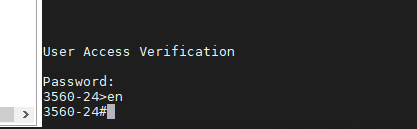
Setting up Telnet:
Alright let’s move into the Global Configuration mode, then into Interface Configuration.
3560-24>en
3560-24#config t
Enter configuration commands, one per line.  End with CNTL/Z.
3560-24(config)#line con 0
We will now be setting line CON 0 with a password and login rights
3560-24>en
3560-24#config t
Enter configuration commands, one per line.  End with CNTL/Z.
3560-24(config)#line con 0
3560-24(config-line)#password cisco
3560-24(config-line)#login
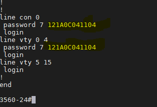
Now lets jump right from CON 0 into VTY 0 4 (Telnet Lines 0 thru 4) and setup the password and login commands.
After we have set both of these up, I like to exit the switch and test to make sure that we can at least get back into the switch before we save to configuration.
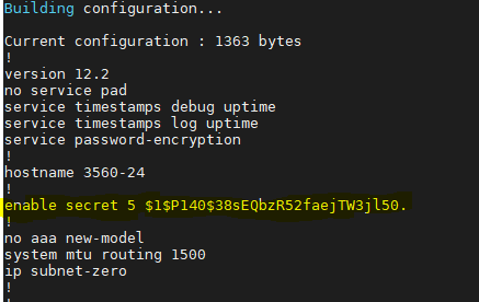
Alright, everything is looking good so let’s configure the Enable password. We will move back into Privileged EXEC mode then into Global configuration mode. Using the command “enable secret <password>” will make our password encrypted. This command does not encrypt our VTY and Con 0 passwords, so we will also run the command “Service Password-Encryption”
3560-24>en
3560-24#config t
3560-24(config)#enable secret cisco
3560-24(config)#service password-encryption
3560-24#exit
Now before you save your configuration. I like to logout and login to verify all passwords are working correctly. Now if you use the command “show running-config” we should see that our enable passwords and line passwords are encrypted.
Setting the Switches IP Address:
We are going to be starting from the EXEC mode and move to the Interface Configuration mode.
3560-24>enable
Password:
3560-24#config t
Enter configuration commands, one per line.  End with CNTL/Z.
3560-24(config)#int Vlan 1
3560-24(config-if)#
Now lets configure Vlan 1 with an IP Address and enable the interface.
3560-24(config)#int vlan 1
3560-24(config-if)#ip address 10.10.10.1 255.255.255.0
3560-24(config-if)#no shutdown
3560-24(config-if)#
17:04:18: %LINK-3-UPDOWN: Interface Vlan1, changed state to up
Now that we have an IP Address on the switch, I also like to setup a default-gateway just in case we have other subnets on our network we need to talk too. If all your devices are on Vlan 1 then you don’t have to do this, but I would highly suggest you do.
3560-24(config)#ip default-gateway 10.10.10.254
Verifying the gateway
3560-24#sh ip route
Default gateway is 10.10.10.254

Host               Gateway           Last Use    Total Uses  Interface
ICMP redirect cache is empty
3560-24#
Saving your Configuration:
Saving your Configuration by either entering “wr” or “copy running-config startup-config”
3560-24#wr
Building configuration...
[OK]

or

(This is the Cisco preferred method)

3560-24#copy running-config startup-config
Destination filename [startup-config]?
Building configuration...
[OK]
3560-24#
Alright, let’s move on to configuring our interfaces with some basic settings.
Basic Access Port:
The two commands we are going to use are “Switchport mode access” and “Switchport access vlan <number>”. The “switchport mode access” command disables DTP – Dynamic Trunking Protocol on the specified interface, which basically turns off trunk negotiation.
3560-24#config t
Enter configuration commands, one per line.  End with CNTL/Z.
3560-24(config)#int fa0/1
3560-24(config-if)#switchport mode access
3560-24(config-if)#switchport access vlan 1
3560-24(config-if)#
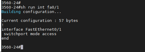
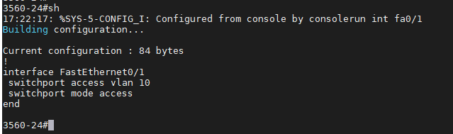
Now lets verify our configuration, you will not see “switchport access vlan 1” as it already in Vlan 1, but if we had configured Vlan 10 we would see it on the port config. By default all ports are in Vlan 1 unless otherwise configured.
Vlan 1:
Vlan 10:
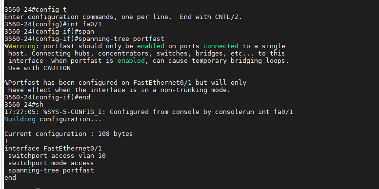
I also like to setup “Spanning-tree Portfast” so the port will come up as fast as possible. You will see a warning message when you enter this command, as it’s important to know not to configure “Portfast” if you are connecting this port to other Hubs, Switches, etc.
3560-24#config t
Enter configuration commands, one per line.  End with CNTL/Z.
3560-24(config)#int fa0/1
3560-24(config-if)#spanning-tree portfast
Here is a screenshot of the warning and the now configured port.
Basic Trunk Port:
This is a basic Trunk port configuration if you have multiple Vans and are needing them to pass to another switch. I’m not going to get into much about trunk ports as I’ll be doing another post and video on this topic, but the below commands will configure a trunk port and pass all configured vlans thru the port.
3560-24#config t
Enter configuration commands, one per line.  End with CNTL/Z.
3560-24(config)#int fa0/2
3560-24(config-if)#switchport trunk encapsulation dot1q
3560-24(config-if)#switchport mode trunk
3560-24(config-if)#end
Verifying configuration:
Extra Knowledge:
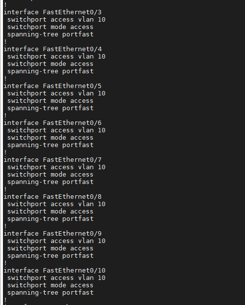
If you want to configure multiple ports at one time you can use the “Interface Range” command to select contiguous ports.
3560-24#config t
Enter configuration commands, one per line.  End with CNTL/Z.
3560-24(config)#int range fa0/3 - 10
3560-24(config-if-range)#switchport mode access
3560-24(config-if-range)#switchport access vlan 10
3560-24(config-if-range)#spanning-tree portfast
You can verify your config using “show running-config” and we will see all the ports configured.


![User Access Verification
password:
3560-24>enab1e
3560-24#de1ete flash: vian .dat
Delete filename [v Ian. dat]?
Delete flash:vlan.dat? [confirm]
3560-24#erase startup-config
Erasing the nvram filesystem will remove all configuration files! Continue? [confirm]
0K]
Erase of nvram: complete
3560-24#
00:03:09: %SYS-7-NV BLOCK INIT: Initialized the geometry of nvram
3560-24#
3560-24#reload
System configuration has been modified. Save? [yes/no] :
proceed with reload? [confirm]'](https://unreal-labs.com/wp-content/uploads/2020/02/image-5.png?w=756)
![This product contains cryptographic features and is subject to United
States and local country laws governing import, export, transfer and
use. Delivery of Cisco cryptographic products does not imply
third-party authority to import, export, distribute or use encryption.
Importers, exporters, distributors and users are responsible for
compliance with U.S. and local country laws. By using this product ymu
agree to comply with applicable laws and regulations. If you are unable
to comply with U.S. and local laws, return this product immediately.
A summary of U.S. laws governing Cisco cryptographic products may be found at:
http://wrw.cisco.com/wwl'export'crypto'tool/stgrg . html
If you require further assistance please contact us by sending email to
export@cisco . com.
cisco WS-C356G-24TS (PowerPC405) ptTcessor (revision DO) with 122886K/8184K bytes of memory.
Processor board ID CAT1018ROXW
Last reset from power-on
1 Virtual Ethernet interface
24 FastEthernet interfaces
2 Gigabit Ethernet interfaces
The password- recovery mechanism is enabled
512K bytes of flash-simulated non-volatile configuration memory.
Base ethernet MAC Address
Motherboard assembly number
Power supply part number
Motherboard serial number
Power supply serial number
Model revision number
Motherboard revision number
Model number
System serial number
Top Assembly Part Number
Top Assembly Revision Number
Version ID
CLEI Code Number
Hardware Board Revision Number
Switch
Ports Model
WS-C356€-24TS
Press RETURN to get started!
73-9897-06
341-0097-02
CAT10172BGN
AZS1€13€80A
WS-C3560-24TS-E
CAT1018ROXW
. 800-26386-62
V02
CO%HO€ARB
ex01
SW Version
SW Image
C356€ - IPSERVICESK9 -M
00:00:24: *LINEPROT0-5-UPDOWN: Line protocol on Interface Vlanl, changed state to down
%SPANTREE-5-EXTENDED SYSID: Extended sysld enabled for type Vlan
%SYS-5-RESTART: system restarted
cisco IOS software, C3560 software (C3560-1PSERVICESK9-M), version RELEASE SOFTWARE (fcl)
Copyright (c) 1986-2007 by Cisco Systems, Inc.
Compiled Thu €5-JuI-G7 22 by antonino
Would ymu like to terminate autoinstall? [yes]](https://unreal-labs.com/wp-content/uploads/2020/02/image-6.png?w=858)

 F")


